Reverse engineering USB devices 101: Understand your target

We’ve learned USB basics and now we are ready to open our USB sniffer and dig into that device we want to reverse but trying to understand what we want to reverse before reversing leads to an easier and less painful work. So first we need to ask ourselves.

How does our targeted device work from a high level perspective?
Understanding the higher level functionality of our targeted device is necessary to successfully reverse it and can provide hints about the inner implementation. In this tutorial our target device is the infamous CH340 chipset. A chipset that bridges the gap between USB computer and serial-based hardware.

What’s a serial communication?
Serial communication is rather broad term but in its inner core means that data is sent one bit at a time. There are tons of different protocols like the venerable RS232, the widely used in the automotive industry CAN bus and even military ones like MIL-STD-1553.

Serial vs parallel

CH340 chipset is one of the multiples USB to serial converters made to add compatibility between PC with USB ports and old serial peripherals. It is not based in any particular protocol so it would be possible to implement different serial protocols using it.

What are the common serial features
There are a lot of different signals in serial protocols but for the sake of simplicity this is the core of a serial communication.
– RXD pin where data is received.
– TXD pin where data is sent.
– Flow control pins to control wether our devices are ready or not ready to send and receive information. Typical signals are RTS/CTS and DSR/DTR

How a USB device would emulate a serial port?
Serial communications need two pin for sending and receiving data. That translates well to USB endpoints so we will probably find two USB IN/OUT endpoints. There is more than one way to send data in USB. What would be the best USB transfer protocol to emulate a serial port? if we look back to the previous post we have:

– Control transfers for setting and reading configuration.
– Bulk transfers to perform large data transactions where data integrity must be guaranteed.
– Iso transfers where what matters is delivery rate and latency.
– Int transfers for shorts bursts of data.

We can easily discard both control and int transfers. Both bulk and iso transfers would be ok for implementing a serial port. ISO endpoints would guarantee faster rates at the expenses of no error correction (not implemented by default in a serial communication either). Bulk transfers don’t guarantee as much speed but data integrity is assured. What transfer a manufacturer would select?
Probably bulk transfers. Serial communications are much slower than bulk transfers so the choice is clear and using bulk transfers you gain error correction. The option is clear.

Serial ports must be configured correctly before sending and receiving data. Usual values are:

– Baud rate.
– Parity.
– Data bits.
– Stop bits.
– Flow control on/off

The CH340 chipset must know the configuration to correctly read RXD and TXD pin voltages and send them through the bulk endpoint. We must assume that these values are sent through control transfers.

There are two kinds of flow control:
– Hardware based: Some lines are asserted raising or lowering the voltage. This is commonly known as out-band signaling because the signaling comes from a different channel than the data.
– Software based: Some bytes are send to indicate whether the flow must stop or resume. This is obviously in-band signaling.

Hardware flow control is what can cause us some headaches here. The signaling goes out of the band so, if we want to be close to the emulated system, we would need a new endpoint acting as flow control. Latency could be very important here. So I would choose between int or iso transfers.
But it could be implemented in a different way. Maybe there is a control transfer to ask for the line status, maybe some packets are sent through the bulk endpoints at fixed intervals with data about the flow control level.

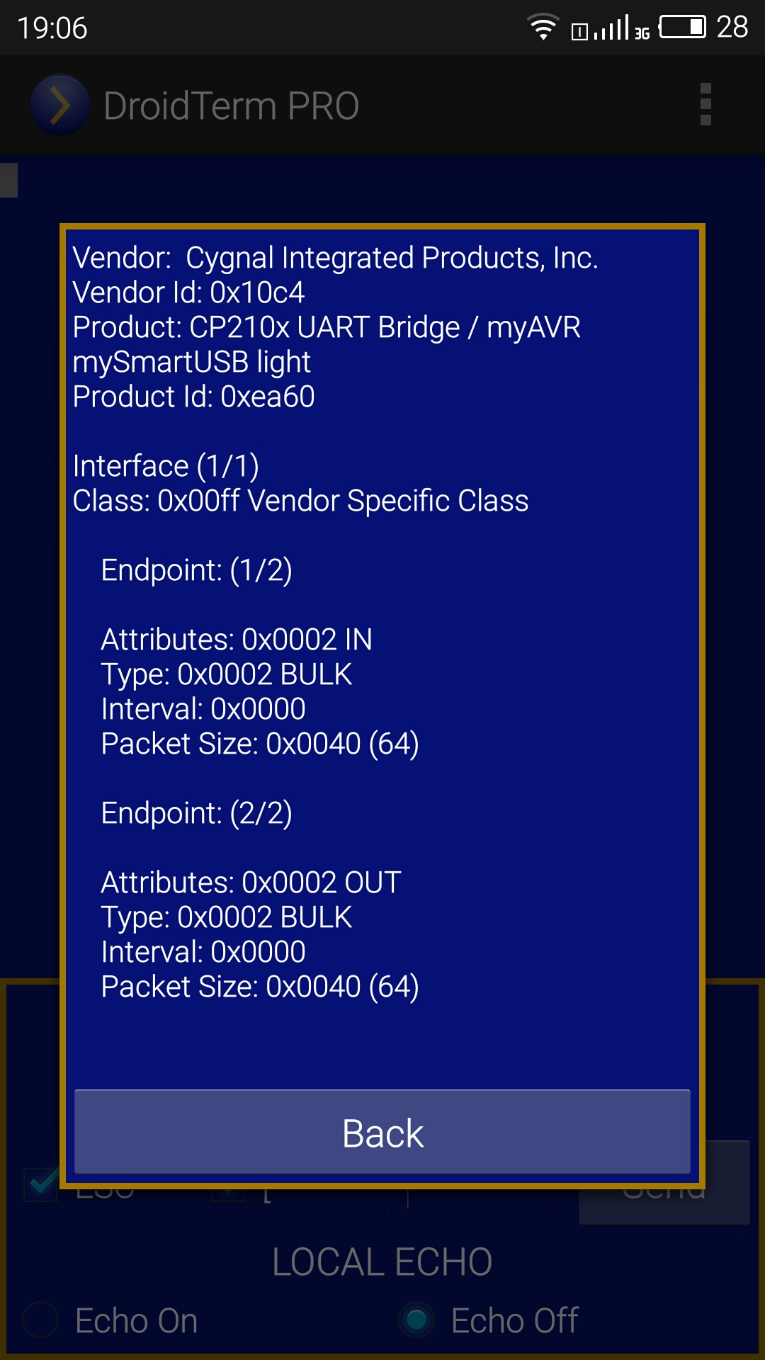
We just outlined what we probably will find in the next step:
– (Very probable) Two Bulk endpoints (IN/OUT) for exchanging data.
– (Very probable)A set of control transfers to configure baud rate, parity, data bits, stop bits and flow control modes.
– (Maybe) A INT or ISO endpoint for emulating hardware flow control.
– (Maybe) A control transfer to check flow control signaling. This approach would require polling at fixed rate.
– (Maybe) Packets sent alongside data with information about flow control.

We now have some understanding of our target. It will help us greatly when surfing through multiple USB calls but we will see that in the last post.

Reverse engineering USB devices 101: Introduction

Reverse engineering USB devices 101: USB Basics

Reverse engineering USB devices 101: USB Basics

We’ve got our USB sniffer working and our targeted USB device is ready for some reverse engineering but before fun gets started, we need to grasp the basics of the USB protocol. Let’s dive a little into the USB realm!

Host-Peripherals
The architecture of USB is host-based where usually a PC acts as a host of one or multiple devices. The host controls everything from detecting new devices, managing correctly data as it flows through the bus, error checking and providing power for every USB connected. USB networks are defined as tiered-star networks where some devices can act as hosts for new devices.

As you can easily realize, most of the hard work is performed by the USB host but peripherals have also some tasks to do. Peripherals need to response to petitions to start communications and must obey the flow control imposed by the host.

When you start your sniffer and start capturing traces, you are watching every packet sent and received by the USB hosts. This communication flow is what it will allow us to understand how our target device is working.

USB classes
The USB standard defines several categories (called device classes) where USB devices can fit in. Every mouse for example shares a core functionality. For this reason virtually every USB mouse fits into the HID class (Human Interface Device). Most common USB device classes are:
– Human Interface Devices(HID)
– Mass Storage
– Printer
– Video

This solved old issues that were present in serial or parallel devices because every manufacturer implemented their protocol on their own ways. For this reason the plug and play is no longer (usually!) plug and pray.

This is not enforced by the USB implementers forum. Manufacturers could produce a USB mouse that doesn’t fit into the HID devices but it would be very impractical. For not so common devices like USB to serial converters this is pretty common. These devices should fit into the CDC (Communication device class) but usually they are defined as a Vendor specific class.

eee

Example of a USB device that doesn’t fit into any standard class, fortunately the CP210x is well documented

Endpoints and transfers
Endpoints can be understood as the sources and sinks of data. Every USB device has at least one endpoint. The mandatory endpoint is called Endpoint 0 and it is where the control transfers issued by the host are directed.

Endpoints are defined by:
– Direction: IN (Device to Host), OUT (Host to Device).
– Transfer type: Control, Bulk, Int, Iso.
– Polling interval.
– Maximum packet size.

There are four different transfers that can be issued for an endpoint. A brief summary of them would be:
– Control transfers: Used for device identification and configuration and directed to endpoint 0.
– Bulk transfers: Used for transferring data when time isn’t critical. Speed is not guaranteed but there is error correction
– Iso transfers: Very suitable for audio and video streaming, delivery rate and latency are guaranteed but there is no error correction.
– Int transfers: Used mainly by HID devices. They guarantee latency only but there is error correction.

Control transfers will allow us to setup our target device exactly as the obscure manufacturer driver is doing. For that reason it’s necessary to dive deeper into control transfers. These transfers are composed of three stages. Setup stage, data stage (optional) and status state. In the setup stage the host transmits the request to the device with all the information about this particular request. If some data is required from host to device or vice-versa will be sent or received on the data stage. Finally the device will inform about the final status of the transfer in the status stage.

Understanding what is sent over the setup stage is needed to replicate how our device target works. In every setup stage 8 bytes are sent to specify what control transfer we are just sending, how many bytes we expect from the data stage, direction of the data stage…
These are the 8 bytes we need to understand:

– bmRequestType:
It’s a byte that specifies the direction of data flow, the type of the request and the recipient
– bit 7: Direction bit (0: device to host 1: device to host)
– bit 6 and 5: Request type bits (00: USB standard request 01: request for a specific USB class 10: vendor specific request
– bit 4 through 0: Recipient bits that define if the request is directed to (00000 device), (00001 specific interface), (00010 endpoint) or other element (00011).

– bRequest:
This byte specifies the request. Every defined request has a unique bRequest value. When bmRequestType is 00 bRequest means a USB standard request. If bmRequestType is set to 01 the request will be specific for a given interface and when bmRequestType = 10 this request is specific for this vendor and product.

– wValue:
Two bytes that the host may use to pass information to the device.

– wIndex:
Two bytes that the host may also use to pass information to the device, usually an index or offset like the interface or the endpoint.

– wLength:
Number of bytes expected on the data stage.

This knowledge is  what I consider a bare minimum to start hacking USB devices but the more you read about it the better. I strongly recommend to you to check out the amazing USB complete for a great USB reference.

We now have a good starting point to begin our reverse engineering feats but before starting I think it is necessary to understand our target device. In the next post We will briefly study what the CH340 chipset does(emulating a serial port). This understanding will really give us a better approach to reverse engineering the infamous CH340/341.

Reverse engineering USB devices 101: Introduction

Reverse engineering USB devices 101: Understand your target

Reverse engineering USB devices 101: Introduction

Because of my work adding support for multiple USB to serial devices in UsbSerial I’ve had to deal with very different chipsets. Some of them like those manufactured by Silicon Labs like the CP2102 or the CP2130 are surprisingly well documented, not only with electrical and mechanical datasheets but also with documentation for driver developers.

Sadly others are not. FT232, one of the most common USB to serial devices out there lacks of official documentation but fortunately those hardcore developers of the Linux and BSD kernel managed to add a very good support long time ago. That is nothing compared to the very obscure CH340/341 chipset.

An example of an USB-Serial cable using CH340 chipset

An example of an USB-Serial cable using CH340 chipset

CH340/341 is a chipset without any kind of documentation besides electrical stuff and it is not well supported outside Windows (I bet it is not well supported even there). With so many custom chipsets and the standard CDC devices these weird chips should have been ignored long time ago. But one shouldn’t underestimate the power of cheapness. With the advent of the maker movement and the Arduino revolution, because of the Arduino open architecture, the market was flocked with Chinese Arduinos clones that replaced the FT232 with the CH340. Ignoring this infamous chip was no longer an option.

I started adapting other implementations but they weren’t working on every CH340 so finally I had to use the last bullet, start from the scratch and reverse engineering this thing! Here it’s the code, if you want to check it out

These posts aim to serve as introduction for people looking for more practical knowledge about USB and eager to reverse engineer USB devices. CH340, although almost non documented, it’s still a very simple USB to serial converter so it is a good candidate for a tutorial. This whole thing may sound complicated but, as you will see, it is easier than expected.

What will we need?
1) A windows computer
Generally speaking, hardware manufacturers put the best of their efforts on developing good Windows drivers for their own products. For some of them supporting of Linux and OS X is secondary in the better cases. This is normally the most common reason for reverse engineering USB or other devices. For this reason we need a Windows computer to be able to see how the device behaves with the manufacturer drivers.

2) USB software sniffer
A good USB software sniffer is mandatory to analyze every packet shared between our PC and the USB devices. There are some alternatives:
– Usbpcap with Wireshark (free and open source)
– Usb analyzer from Eltima software
– USBTrace from Sysnucleus
– USBlyzer

All of them should do the job but in my humble opinion, USBlyzer is by far the best of all them at the expense of a high price for hobbyists. Choose the right one for your needs.

What’s next?
Before starting, some knowledge of the USB protocol is required. This will be explained in the next post. Stay tuned!

Reverse engineering USB devices 101: USB Basics

Reverse engineering USB devices 101: Understand your target

UsbSerial SPI support

UsbSerial already supports most of the common USB to serial chips out there but these chips are pretty “serial standard” and as you probably know there are a lot of different serial architectures.

SPI is one of them. Developed by Motorola in the 80’s allows synchronous communication between one master devices and nth number of slaves devices.

A typical SPI configuration with one SPI master and three SPI slaves.

Someone requested support for CP2130 Usb to SPI bridge and, as always I like to emphasize I am always open to support new devices but this one is not as “serial generic” as the others (Windows even doesn’t see it as serial port). It is specifically designed to bridge USB to SPI. SPI interfaces presents different capabilities compared to a simple UART. Clock signal is provided by the master so greater speeds than using simple UARTS are possible and there are nth SSX lines to select different slaves.

Because of these characteristics a new interface specific for SPI was necessary for UsbSerial but I’ve tried to preserve the same philosophy of use that governs UsbSerial. Keep in mind that SPI support is still in beta state and this interface could change due to adding new devices.

  //Common SPI operations
  boolean connectSPI(); // connect SPI device
  void writeMOSI(byte[] buffer); // send data to the selected slave via MOSI. Asynchronous call
  void readMISO(int lengthBuffer); // read data sent from the selected slave via MISO.  Asynchronous call
  void writeRead(byte[] buffer, int lenghtRead); // write and read at the same time. Asynchronous call
  void setClock(int clockDivider); // set clock speed
  void selectSlave(int nSlave); // select slave
  void setMISOCallback(UsbMISOCallback misoCallback); // set MISO callback
  void closeSPI(); // close SPI device

  // Status information
  int getClockDivider(); // get clock divider
  int getSelectedSlave(); // get selected slave
  
  // Miso callback for received data
  interface UsbMISOCallback
  {
      int onReceivedData(byte[] data);
  }

  // CP2130 speed values
  CP2130SpiDevice.CLOCK_12MHz
  CP2130SpiDevice.CLOCK_6MHz
  CP2130SpiDevice.CLOCK_3MHz;
  CP2130SpiDevice.CLOCK_1_5MHz;
  CP2130SpiDevice.CLOCK_750KHz;
  CP2130SpiDevice.CLOCK_375KHz;
  CP2130SpiDevice.CLOCK_187_5KHz;
  CP2130SpiDevice.CLOCK_93_75KHz;

Previous examples of UsbSerial provides a good start keeping in mind the minor changes.

// Define MISO callback
private UsbSpiInterface.UsbMISOCallback misoCallback = new UsbSpiInterface.UsbMISOCallback()
{

  @Override
  public int onReceivedData(byte[] data) {
     // Your code here
  }
};

//...

// Setup SPI communication
UsbSpiDevice spi = UsbSpiDevice.createUsbSerialDevice(device, connection);
if (serialPort != null) {
  boolean ret = spi.connectSPI();
  if(ret){
    spi.selectSlave(0); //select slave 0
    spi.setClock(CP2130SpiDevice.CLOCK_3MHz);
    spi.setMISOCallback(misoCallback);
  }
}

// Write and read operations
spi.writeMOSI("Hola!".getBytes()); // Write "Hola!" to the selected slave through MOSI (MASTER OUTPUT SLAVE INPUT)
spi.readMISO(5); // Read 5 bytes from the MISO (MASTER INPUT SLAVE OUTPUT) line. Data will be received through UsbMISOCallback
spi.writeRead("Hola!".getBytes(), 15); // Write "Hola!" and read 15 bytes synchronously

//Close spi device
spi.closeSPI();

As I previously said, it is still in beta state and only CP2103 chipset is supported. I would really appreciate any feedback you could give me about this feature to further improvements.

Happy hacking!

CH340/341 improved support in UsbSerial 4.2

UsbSerial supports the problematic CH340/341 chipset from 3.0 but the implementation lacked of some necessary features. Finally I managed to get some time to improve CH340 and I gladly announce that CH340/341 support has taken a very long leap!

Current Features
– Broader range of baud rates supported: 300, 600, 1200, 2400, 4800, 9600, 19200, 38400, 57600, 115200, 230400, 460800, 921600
– Flow control support for RTS/CTS and DTR/DSR.
– All parity modes.

With this new driver the support for the Arduino clones should be better.

More information about UsbSerial

Happy hacking!

Apps and projects using UsbSerial

When I started UsbSerial to fill my own needs I never really expected it would be used for other programmers to their own apps and project but eventually it happened! These are some of the projects where it is used besides DroidTerm and DroidTerm PRO. If you want your project listed here just contact me 🙂

Aprsdroid
APRSdroid is an Android application for Amateur Radio operators that allows to report your position to the APRS (Automatic Packet Reporting System). UsbSerial is used to connect TNC’s (Terminal node controllers) to the Android device. I am not sure if this feature is in release mode but there are interesting developments in the APRSDroid github.


Mouse4All
The guys from BLECentral have developed a project to allow people with severe movement limitations use an Android tablet. I personally saw it and it is an awesome example of how technology can enhance people’s life! UsbSerial is used to connect the special mouse to the tablet.

Akvo Caddisfly, the water quality testing kit
Akvo is a not-for-profit foundation that creates open source, internet and mobile software and sensors. One of their projects is Akvo Caddisfly, an Android application to test water quality in a very low cost way. UsbSerial is used to communicate with the sensors to test water’s conductivity. The app is open-source and its code is hosted on Github

Musethereal

MuseTheReal is an amazing project that shows how science, engineering and fashion can be put together to create something amazing. MuseTheReal showcases the relationship between music and consciousness. This project performs in the MakeFashion gala in Calgary, Canada. A gala where fashion and wearables is combined with fashion. The code is available on Github.

Check out this interview with Angie, Ksenia and the rest of the team!

A DIY Android Auto

This is a great example of what a hacker really is. Dennys from Ukraine is developing a DIY Android Auto for his 2009 Kia Ceed. A great DIY example.

A UsbSerial wrapper for Delphi

A UsbSerial wrapper for the Basic4Android development

UsbSerial now allows using flow control signals RTS/CTS and DTR/DTS!

Finally I’ve managed to get some time to implement hardware flow control in UsbSerial! It is probably the most trickiest part of treating with these chipsets because every single one handles this in a very particular manner.

– CP210x devices check the modem status through a usb control transfer, so I was forced to perform a polling in a new thread every X time to check for changes.
– FTDI devices has a more clever way. Every 40 ms a 2-byte package is sent to the host which contains information about the modem signals and the flag errors.
– PL2303 (not implemented yet) have a USB INT endpoint which it is the obvious candidate where modem status data will be received, no really sure yet though.
– CH340/341 also have a USB INT endpoint but polling is also possible and, because some Android inner bugs, the best way to poll the lines state.

Let’s see how it works with an example

UsbDevice device;
UsbDeviceConnection usbConnection;
...
UsbSerialDevice serial = UsbSerialDevice.createUsbSerialDevice(device, usbConnection);
serial.open();
serial.setBaudRate(115200);
serial.setDataBits(UsbSerialInterface.DATA_BITS_8);
serial.setParity(UsbSerialInterface.PARITY_NONE);
serial.setFlowControl(UsbSerialInterface.FLOW_CONTROL_RTS_CTS);

This is basically the same as the previous versions but now the setFlowControl is meaningful. Now that We have our connection configured to pay attention to the RTS and CTS lines let’s define our callback to receive or status changes.

private UsbSerialInterface.UsbCTSCallback ctsCallback = new UsbSerialInterface.UsbCTSCallback() {
        @Override
        public void onCTSChanged(boolean state) {
            //Your code goes here!
        }
    };

And pass the reference to the UsbSerialDevice object

serial.getCTS(ctsCallback);

Now We know when the status of the line change. I will be also executed in the beginning to know what is the status of the line. If you need to raise the RTS or the DST lines jut write these lines.

serial.setRTS(true); // Raised
serial.setRTS(false); // Not Raised
serial.setDTR(true); // Raised
serial.setDTR(false); // Not Raised

PL2303, CH340/341 and CDC still lack of this feature. If you find something wrong just let me know. Happy crafting! 🙂

EasyFTP: A Simple FTP Client

Let’s face it, app designing is nowadays almost as important coding that is the reason why, as not so new year proposal I am trying to improve my design skills (I won’t be heavy latte consumer designer anytime). One niche of apps that usually don’t show a minimum amount of good design are utilities. My app DroidTerm which has a retro blue aesthetics as a matter to overcome my designing limitations has been described as “easy to use and straightforward”.

For that reason I started EasyFTP, just a simple to use FTP client for Android. Some important features are yet missing but the core is pretty solid. Let’s describe some of the characteristics of this client:

1)FTP Session menu
A simple dialog with fields for host, user, password and port (if empty will use port 21).
S51031-173517
The input of the host can be a hostname or a ip address. Everytime a session is started the data is stored to allow easiest access later through the autocomplete Android feature.

S51101-134834

Press the flash button to start your session!

2) File transfers
This is how a typically EasyFTP session looks like:
S51031-173812
Local files are shown in the upper half and remotes in the lower. Drag and drop files between them and keep in mind that the transfers are performed asynchronously which means you can keep transferring files or browsing through directories while operations are being performed. When there are operations queued a load symbol appears right to the remote path.

Stay tuned for more upgrades!

DroidTerm PRO 1.2: Multi Character Encoding Support

I am happy to announce that DroidTerm PRO finally supports different character encodings which can be useful to connect with some legacy systems that still uses things like the CodePage 437 to extend ASCII. Current character encodings are:

– ASCII
– ISO 8859-1
– UTF-8 (set by default)
– UTF-16
– CP437

To change the character encoding, press the menu button in the upper right corner and select character encoding.
Screenshot_2015-09-24-18-39-35

There are tons of legacy encodings there so I probably will add some of them in next months.

More information about DroidTerm Pro and its free version
Happy crafting!

DroidTerm 7.1 and DroidTerm PRO 1.2: Usb Serial port terminal for Android

Finally new updates on DroidTerm! I managed to fix the first and foremost bug that was present on previous releases of DroidTerm, the unresponsive scroll when data was received. The text renderer is completely new and it offers and smooth scroll and keeps the app responsive.

After much thought I’ve decided to split DroidTerm into two apps, one free (with ads) that contains the same features, plus the scroll fix, than previous versions and other paid version with no ads and more features.

DroidTerm FREE
DroidTerm PRO

My intention is to keep the Free version stable as it is useful for the common user and add more complex features to the PRO version.
Try first the free sure to be sure it fits your needs, if you need the PRO features or you find DroidTerm useful and you want to help in its further development consider buying the PRO version.

If you prefer you can donate via Paypal tu support further improvements

DroidTerm PRO new features: VT100 Terminal emulator
DroidTerm PRO allows to send a subset of the ANSI control escape sequences. Designing a good interface to support this feature has been more complicated than I thought. Instead of relying purely on the Android keyboard the ‘ESC’ and the ‘[‘ button are check buttons that can be set to ON or OFF, the rest of the command must be written in a field. When the command ready, press the ‘Send’ button.

Screenshot_2015-09-10-22-51-07
ESC[2J escape sequence will erase the screen and move the cursor to home

Some systems echo back whatever you send but in some configurations need local echo. Local echo can be ON/OFF easily by the checkboxes below the the ANSI escape sequences.

DroidTerm Pro new Feature: Different character encodings

DroidTerm features explained in previous posts

USB Viewer
Logs and Hex viewer
Log viewer and Bulk transfer
Connection profiles
Profiles automatically create a default log file. LF CR and LF-CR End of line options added
CH340/CH341 supported, those cheap Arduino clones should be working now 🙂

Both versions use UsbSerial to handle serial port which is free, open source and can boost your projects too!

DroidTerm started as a little serial port terminal, it was buggy as hell in the first release with a very slow scroll and a lack of features but now it is unrecognizable! I started this because other options for serial ports were disappointing and I can state that right now is probably the best out there for Android, probably still not the PuTTy replacement for Android but who knows.. 🙂

Happy crafting!