We’ve got our USB sniffer working and our targeted USB device is ready for some reverse engineering but before fun gets started, we need to grasp the basics of the USB protocol. Let’s dive a little into the USB realm!
Host-Peripherals
The architecture of USB is host-based where usually a PC acts as a host of one or multiple devices. The host controls everything from detecting new devices, managing correctly data as it flows through the bus, error checking and providing power for every USB connected. USB networks are defined as tiered-star networks where some devices can act as hosts for new devices.
As you can easily realize, most of the hard work is performed by the USB host but peripherals have also some tasks to do. Peripherals need to response to petitions to start communications and must obey the flow control imposed by the host.
When you start your sniffer and start capturing traces, you are watching every packet sent and received by the USB hosts. This communication flow is what it will allow us to understand how our target device is working.
USB classes
The USB standard defines several categories (called device classes) where USB devices can fit in. Every mouse for example shares a core functionality. For this reason virtually every USB mouse fits into the HID class (Human Interface Device). Most common USB device classes are:
– Human Interface Devices(HID)
– Mass Storage
– Printer
– Video
This solved old issues that were present in serial or parallel devices because every manufacturer implemented their protocol on their own ways. For this reason the plug and play is no longer (usually!) plug and pray.
This is not enforced by the USB implementers forum. Manufacturers could produce a USB mouse that doesn’t fit into the HID devices but it would be very impractical. For not so common devices like USB to serial converters this is pretty common. These devices should fit into the CDC (Communication device class) but usually they are defined as a Vendor specific class.
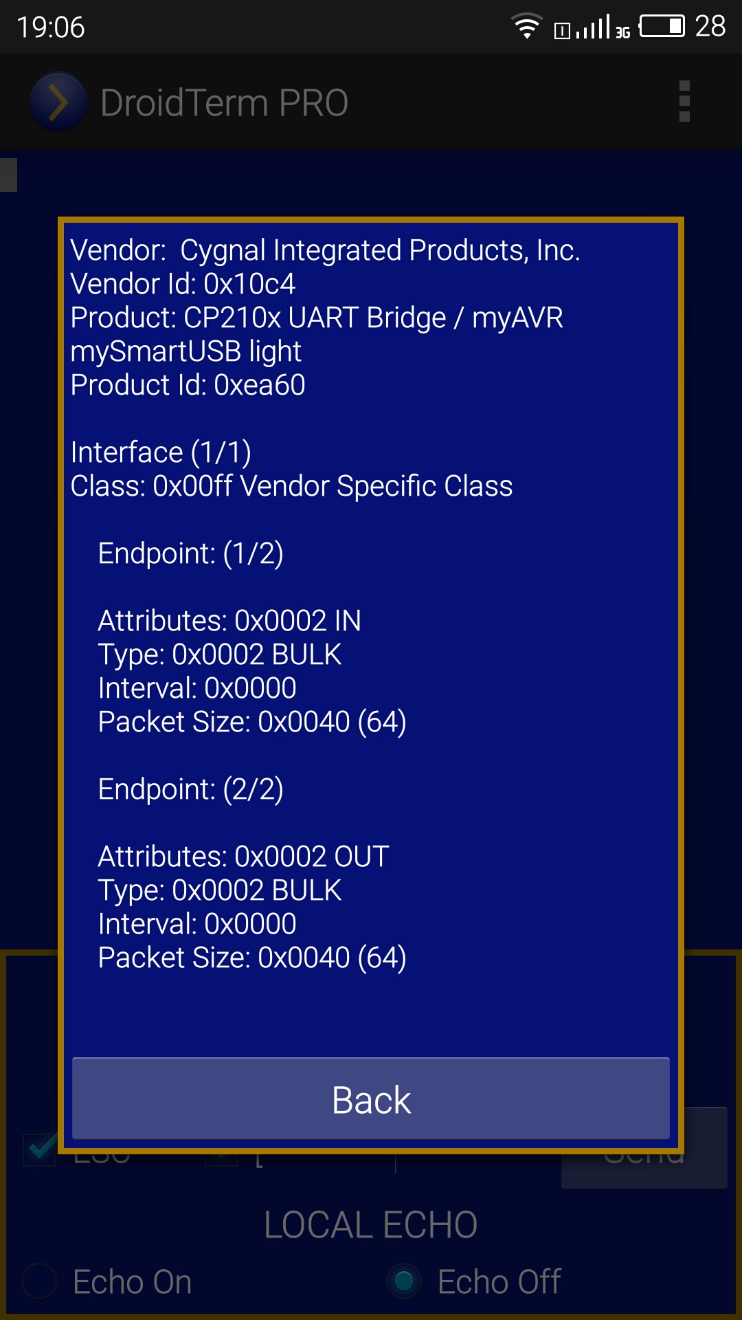
Example of a USB device that doesn’t fit into any standard class, fortunately the CP210x is well documented
Endpoints and transfers
Endpoints can be understood as the sources and sinks of data. Every USB device has at least one endpoint. The mandatory endpoint is called Endpoint 0 and it is where the control transfers issued by the host are directed.
Endpoints are defined by:
– Direction: IN (Device to Host), OUT (Host to Device).
– Transfer type: Control, Bulk, Int, Iso.
– Polling interval.
– Maximum packet size.
There are four different transfers that can be issued for an endpoint. A brief summary of them would be:
– Control transfers: Used for device identification and configuration and directed to endpoint 0.
– Bulk transfers: Used for transferring data when time isn’t critical. Speed is not guaranteed but there is error correction
– Iso transfers: Very suitable for audio and video streaming, delivery rate and latency are guaranteed but there is no error correction.
– Int transfers: Used mainly by HID devices. They guarantee latency only but there is error correction.
Control transfers will allow us to setup our target device exactly as the obscure manufacturer driver is doing. For that reason it’s necessary to dive deeper into control transfers. These transfers are composed of three stages. Setup stage, data stage (optional) and status state. In the setup stage the host transmits the request to the device with all the information about this particular request. If some data is required from host to device or vice-versa will be sent or received on the data stage. Finally the device will inform about the final status of the transfer in the status stage.
Understanding what is sent over the setup stage is needed to replicate how our device target works. In every setup stage 8 bytes are sent to specify what control transfer we are just sending, how many bytes we expect from the data stage, direction of the data stage…
These are the 8 bytes we need to understand:
– bmRequestType:
It’s a byte that specifies the direction of data flow, the type of the request and the recipient
– bit 7: Direction bit (0: device to host 1: device to host)
– bit 6 and 5: Request type bits (00: USB standard request 01: request for a specific USB class 10: vendor specific request
– bit 4 through 0: Recipient bits that define if the request is directed to (00000 device), (00001 specific interface), (00010 endpoint) or other element (00011).
– bRequest:
This byte specifies the request. Every defined request has a unique bRequest value. When bmRequestType is 00 bRequest means a USB standard request. If bmRequestType is set to 01 the request will be specific for a given interface and when bmRequestType = 10 this request is specific for this vendor and product.
– wValue:
Two bytes that the host may use to pass information to the device.
– wIndex:
Two bytes that the host may also use to pass information to the device, usually an index or offset like the interface or the endpoint.
– wLength:
Number of bytes expected on the data stage.
This knowledge is what I consider a bare minimum to start hacking USB devices but the more you read about it the better. I strongly recommend to you to check out the amazing USB complete for a great USB reference.
We now have a good starting point to begin our reverse engineering feats but before starting I think it is necessary to understand our target device. In the next post We will briefly study what the CH340 chipset does(emulating a serial port). This understanding will really give us a better approach to reverse engineering the infamous CH340/341.
